
You are using an out of date browser. It may not display this or other websites correctly.
You should upgrade or use an alternative browser.
You should upgrade or use an alternative browser.
Any faults in Wiring Diagram?
- Thread starter BrettD
- Start date
Pudsey Bear
Forum Member
I used 10mm2 for everything just in case I want to add something inline later but to my unexpert eye it looks pretty good to me
SquirrellCook
Forum Member
I hope the batteries are sealed, or they might leak! ")
Pudsey Bear
Forum Member
Sorted

wildebus
Forum Member
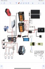
I would say that is not a diagram to follow
The pair of batteries are not configured in a balanced manner, so you will not get an even optimised use out of them.
There seems to be no circuit for Vehicle Charging anywhere?
10mm2 cable is a bit skinny I would say (for example, the last battery banks I installed yesterday and the day before I used 35mm2 cable to cope with the charging demands and inverter use).
Breakers rather than fuses can be problematical (they rarely operate at the rating promised). There is also a breaker/fuse missing from the Victron Mains Charger circuit (yes, the charger has a fuse on it, but that is device protection, not cable protection - which is the reason you add these fuses).
What cable size are you looking at on the various load circuits? The gauge depends on the load (a compressor fridge will require much thicker than LED lighting, for example).
BrettD
Forum Member
Thank you for the replyI would say that is not a diagram to follow
The pair of batteries are not configured in a balanced manner, so you will not get an even optimised use out of them.
There seems to be no circuit for Vehicle Charging anywhere?
10mm2 cable is a bit skinny I would say (for example, the last battery banks I installed yesterday and the day before I used 35mm2 cable to cope with the charging demands and inverter use).
Breakers rather than fuses can be problematical (they rarely operate at the rating promised). There is also a breaker/fuse missing from the Victron Mains Charger circuit (yes, the charger has a fuse on it, but that is device protection, not cable protection - which is the reason you add these fuses).
What cable size are you looking at on the various load circuits? The gauge depends on the load (a compressor fridge will require much thicker than LED lighting, for example).
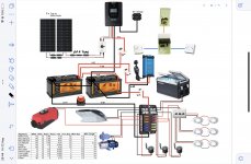
Made some changes then,
Changed the breakers to ANL fuses
Changed the inline fuse between solar panels and charge controller to 20amp as this was wrong to begin with
I’ve added my spreadsheet of what fuse and wire size I have worked out for each appliance (hope it makes sense)
I’ve also added a battery cut off switch on the negative wires from the blade fuse holder, hope that is correct?
Also regarding the vehicle charging, decided to go against it as we already have the solar and mains charger and most of the time we’ll be on a campsite after a few days at least so didn’t think we’d need it
What is the best way to wire the batteries as well? I’ve just took this way from different YouTube videos?
Attachments
wildebus
Forum Member
Firstly, there are lots of different ways to do things.
Generally they all work, but some work better than others and have significant advantages.
I would recommend you have a read of this chaps site - https://caravanchronicles.com/guides/how-to-connect-two-batteries-in-parallel/ - it has clear diagrams and explanations of not just how, but why, multiple batteries should be configured in certain ways.
Now there is a very well respected YouTuber who has wired his self-build in a similar way to how your diagram was. To be frank, that is not the way to do it, but because he has a popular channel, people copy it. And yes, it works, but not optimally - and if you are starting fresh, why not do it using the right standards?
Ref cut-offs, I personally isolate the POS rather than the NEG, but you could do either as long as you isolate the NEG fully i.e. at the battery bank before it starts distributing out.
(And talking about an isolation switch/battery cutoff, it you look at the diagram you originally had, and try to work out where to put an battery cut-off, you can see it is impossible to do. That is one of the reasons why that battery wiring is not correct)
I would also recommend the use of a 'catastrophic' fuse between battery and charge/load connections. A switch will isolate the battery manually when you are there to do it, but if something particularly unwelcome occurs, this fuse will protect against that. At around £10 for the cost of a fuse holder and fuse, it is a small price to pay for the extra protection and piece of mind.
SquirrellCook
Forum Member
Utube, I’ve done it once and now I’m an expert. It should have a warning. “For entertainment only”
Pudsey Bear
Forum Member
Very true, you should always watch at least 5 YT videos then you will have 5 right ways of doing it the wrong way.
To be fair, for most stuff YT is invaluable there are some very generous-minded helpful people out there.
To be fair, for most stuff YT is invaluable there are some very generous-minded helpful people out there.
wildebus
Forum Member
It can be very informative but have to be cautious.
I remember a few years ago I was at a show and was asked by someone for some help with his conversion. He had been following a certain channel (the one I mentioned earlier) and been copying the guys build as he went along. But then he was left high and dry when this person decided what he was doing was wrong and started again! I bet the guy I spoke to was not the only person who had been following and copying, not really knowing what he was doing, and left in a dead end
I don't bother commenting on the videos that are posted like that as found no point, as because when it is a popular channel, nothing on them can possibly be incorrect in the eyes of the brethren.
Pudsey Bear
Forum Member
I don't think I've ever really bothered with electrical videos although I do watch Big Clives channel as he's just hilarious, I prefer to come on a forum and ask, but present company excepted that too can be dodgy.
wildebus
Forum Member
He is entertainingI don't think I've ever really bothered with electrical videos although I do watch Big Clives channel as he's just hilarious, I prefer to come on a forum and ask, but present company excepted that too can be dodgy.
There are a few channels talking about electrical things that I enjoy and they tend to be the ones where the channel owner just wants to share their enthusiasm about the subject (very much like Big Clive I would say), rather than channels that push stuff and go on about "like and subscribe" and trying to get to 100,000 subscribers, etc.
Pudsey Bear
Forum Member
Some of the best channels only have a few thousand subscribers. Kris Habour is good, and very informative, you might like him, and I like Waylons old iron, he's just entertaining, also trail mater for pure skills.
BrettD
Forum Member
Right so regarding wiring of the batteries, unfortunately I don’t have my IPad with me so I’m unable to change the diagram but basically what I need to do is have all negative wires going to let’s say battery A and then another negative wire linking battery A to B. Then all positive wires attached to battery B and again just one other wire linking positives from battery B to A
Is that correct?
Is that correct?
Pudsey Bear
Forum Member
Hmm, Re Neg wiring I was told it was best to put them direct to the chassis as near to the battery as possible, I thought this was a good idea as the chassis manufacturer did the same.
But I'm not a sparky so ignore me.
But I'm not a sparky so ignore me.
wildebus
Forum Member
Have a look at that link I posted for Caravan Chronicles is the first step.Right so regarding wiring of the batteries, unfortunately I don’t have my IPad with me so I’m unable to change the diagram but basically what I need to do is have all negative wires going to let’s say battery A and then another negative wire linking battery A to B. Then all positive wires attached to battery B and again just one other wire linking positives from battery B to A
Is that correct?
Then you make a battery bank by connecting the batteries together in the optimum way. For two batteries, POS to POS and NEG to NEG;
If they are next to each other, just connect; if the cables to connect them together has to go through any metalwork or distance, then you need to protect the cables with fuses to cover shorting of cable to ground (for example, I installed a pair of batteries this week in a van where each battery was in a cab seat base, so fitted a fuse to both ends of the POS to POS cable for safety).
Once you have the above covered, then yes, BAT A has all the +ves and BAT B has all the -ves. Remember all cables need to be fuse protected and rather than stacking up lots of terminals on the battery post, use a fuse block to make it tidy.
You could run the various devices (EHU Charger, Solar Controller, Cable to Hab Electrics, etc) to a Fuse Block such as this - https://amzn.to/3Qxw5No
and then a single cable from fuse block to battery (via a Catastrophic Fuse and Isolation Switch such as these - https://amzn.to/3bUw5Z8 and https://amzn.to/3pfmGyb ).
And repeat for the -ve cables from these devices, maybe with a shunt between the bat -ve and fusebox for a battery SOC monitor such as this - https://amzn.to/3pd48Pn.
Oh, and use proper cable from battery to fuse block - work out what all the maximum loads are likely to be - both now and in the future (maybe you will get an inverter? or fit a B2B?). Get cable to suit (and upgrade to bigger!). That length of cable is short and the cost saving to stay at 10mm2 is nothing in the overall scheme of the installation.
wildebus
Forum Member
Manufacturers do that as they save money on cableHmm, Re Neg wiring I was told it was best to put them direct to the chassis as near to the battery as possible, I thought this was a good idea as the chassis manufacturer did the same.
But I'm not a sparky so ignore me.