Updating VW T5 to an Off-Grid Camper

wildebus

Forum Member
This is not my own van, but I think it may be of interest as I will be touching a few different areas whilst updating the camper which may be of use to builders?

This is the Campervan:

VW T5 T32 Kombi
by David, on Flickr

Over the next two-three weeks the following will be done:
  1. Upgrade to 2 x Leisure Batteries with 190Ah Total Capacity
  2. Fit 220W PV Array to the Pop-Top + Victron MPPT Controller + Smart Battery Sense
  3. Install Upgraded Mains Charger
  4. Install 1500W PSW Inverter
  5. Fix Eberspacher Wiring to use the temp sensor in the 801 Controller
  6. Install Victron BMV Battery Monitor
  7. Install System Monitoring hub (Raspberry Pi running Victron GX s/w)
 

wildebus

Forum Member
Day 0 - Preliminary Stripdown and Evaluation

First step is to see what we are dealing with....

Stripped out Cab area ready to get access to undercarpet area and make it easier to route cables

First - remove seats to get to various bits installed (battery, split charge, mains charger, etc)

Cab - Seats Out
by David, on Flickr

Lots of unneeded holders on the passenger seat that can be removed to make space (this is typical of VW T5 vans as there are so many options available)

T5 Passenger Seat - Wiring
by David, on Flickr

Batteries and all the other bits and pieces can now be removed and then the seat bases themselves

Cab Stripped
by David, on Flickr

Some items to note:
Split Charge is a 140A VSR with 6mm cable used between Batteries - IMO quite poor and not really even adequate for a small B2B Charger Setup so will be replacing that with 16mm cable to minimise Volt Drop and maximise performance.
There is a 6mm cable from the Leisure Battery to the PMS Power Management/Distribution System at the rear - that is ok in terms of current carrying ability but because I am fitting chargers in the rear (a 30A AC Mains and a 20A MPPT Controller) I will upgrade that 6mm to more 16mm Cable to minimize Volt Drop and maximise charging quality.
 

wildebus

Forum Member
Not made a lot of progress to take it from Day 0 to Day 1, but have run the new 16mm Cable from Front to Back, plus the BMV RJ-12 Cable.
Also rewired one of the 240V sockets ready to be fed by the inverter instead of the EHU.

The Solar Installation will be this kit - Lensun® 220W(2x110w) Sunpower Black ETFE Flexible Solar Panel, Top Quality NOT the Cheap PET Flexible Solar Panel . I have heard of them of course, but not actually used any Lensun kit before, so had some email and telephone conversations with them (office is only in China despite the UK and US phone numbers) to get a feeling for them. Just a little wary handing over a few hundred quid to a company with no Local presense!
All seemed good, so placed the order Tuesday Morning and the panels arrived this (Thursday) morning with UPS, so pleased with the fast service there. Not unpacked them and won't be able to do so until probably Monday as away at a show this weekend and need to prep for that, but I am sure it will be all good (would not be able to test them very well anyway with the current weather)
 

wildebus

Forum Member
Day 1 - Fitting out the Electrics rear of the Cab

a) Inside the Rear Cupboard

Next step was to commence the actual fitting....

This is the area I have available for the additions

Cupboard
by David, on Flickr
Below is a breakdown for each part...

So after quite a bit of musing and trying to place everything for decent cable routing, accessibilty and minimal incursion into the storage space, I decided on this layout

Cupboard Additions
by David, on Flickr

Anything outside the red dotted lines was already there and pretty well left as was (except "4" - more later).

Additions are:
1) Victron IP22 30A Multi-Stage Bluetooth Connected AC Charger. Nice Unit with a key feature being its near-silent operation - and when put into 'Night' mode via either the Bluetooth App or hitting a button on the unit itself, it is totally silent

2) Victron MPPT 100/20 SmartSolar Controller. Top quality unit capable of supporting upto 330W worth of PV Panels. Like the AC Mains Charger, this is a Bluetooth enabled Device. It also has a VE.Direct Port (more on that later)

3) Multiway/Combi Fuse Holder. I use these quite a lot as they are very handy and compact.
I fitted a pair of 16mm cables (+VE & -VE) running from the Battery Bank in the front to the cupboard. Originally these were 6mm cables but to get the right quality of charging from either Mains or Solar, I wanted to eliminate voltage drops as far as possible. I then use this Combi unit to distribute the 16mm cable connection to the various devices as well as adding individual fuse protection - AC Mains Charger (40A), MPPT Controller (30A) and the existing PMS3H Distribution Unit (40A). Also feeds a Raspberry Pi with a 5A Fused connection.
This combi supports 4 x Midi Fuses plus a Mega Fuse. I am not using the Mega Fuse connection as not needed here and instead using the spare stud as a GROUND distribution for the added devices.

4) This is actually an existing 240V AC Mains Socket. I rewired it so it would be fed by the Inverter 240V rather than the EHU

5) Victron BMV-712 Battery Monitor. Like the MPPT Controller, this is both Bluetooth enabled and has a VE.Direct Port

6) Raspberry Pi running Victron Venus GX Operating System. This is connected to both the BMV-712 and the 100/20 MPPT unit with VE.Direct--USB Cables; Plus a USB GPS unit.
It is also connected with a wired Ethernet Connection to a surplus Internet Wifi Router for local Intranet use, and a WiFi connection to any available hotspots.
Having the local Router means it is easy to connect to the Victron (Pi) GX system and view the electrics at any time. This is the 'infotainment system' fitted in the dashboard connected to the Remote Console of the Venus GX system

Head Unit with Remote Console
by David, on Flickr
(this is a view part-way though the install so not all info is showing yet)

The way the System works, if the Pi sees an active unit on the Wired connection, it will try to use that connection to get onto the Internet. But this router has no internet (WAN) running. So in order to be able to easily switch between the Local connection and the World Wide Web, I adapted the router to run off a regulated 12V DC supply, and that is connected to the MPPT Controllers LOAD connection. The point here being that the LOAD output on the Victron Solar Controller can be turned on and off using the Bluetooth App. And so you can have remote control over the systems network access and connectivity using the same Victron app which is used to setup/control the mains charger, the solar charger AND the battery monitor (this is one of the reasons I love this Victron gear! :) )

This setup will give the owner comprehensive info on the electrical system both when with the vehicle and also remotely (important for this owner as he spends consecutive weeks away off-shore).
 
Last edited:

wildebus

Forum Member
Day 1 - Fitting out the Electrics rear of the Cab

b) Flush Mounting Displays

Now I am much more about electrics design and setup and much less about carpentry and woodworking, but sometimes need to just do it! And this setup needed two things installed and to look pretty as they are on view. So a few words on how I did this (not saying it is the best or right way to do it, just how I do it)

1) Victron BMV-712 Battery Monitor.
This needs a 52mm round hole to mount into.
The location agreed for this was in line with some existing devices, so first out with the blue tape to protect the shiny surface from any marks...

Location for BMV
by David, on Flickr

Then using the screws on the CBE Frames as a centre guide to ensure we were in line marked the horizonal and chose the middle point to for drilling ...

Location for BMV Marked Up
by David, on Flickr

Nice round hole drilled ...

51mm Hole Made
by David, on Flickr

Tool Talk: Now I have a few hole saw sets (at least 4 and probably more) but there is always one specific set I reach for first - the Bosch Progressor Set with Power Change.
Now if you have used hole saws very much the chances are you will have had to deal with two things - 1) the material getting stuck in the holesaw and having to faff around digging it out when you just want to get on with the job; and 2) the hole saw getting jammed solid onto the drill attachement and near impossible to remove. The reason I always try and use the set I linked to above is because of the Power Change feature. It eliminates the 2nd problem and makes the first one a matter of seconds to sort out.


Tape off, sawdust cleaned away, covers back on the CBE Devices and BMV installed - not a bad colour match either!

BMV Fitted
by David, on Flickr

Now the Holesaw kit I used didn't have a 52mm saw, just a 51mm but I used it anyway as I knew [from previous installs] it would fit, but that missing 1mm does mean it is a very tight fit and doesn't just drop into place.


2) Inverter Remote Control
The other Device for flush fitting is the Remote on/off control display for the 1500W PSW Inverter.

Same initial process as with BMV - tape out and mark position...

Inverter Control - Marking up
by David, on Flickr

Tool Talk: As you can see, this needs a square hole, and as I was out of square hole saw kits I had to use a different tool - I used a Bosch PMF 180-E Multi-Tool. The Link takes you to a newer version (I bought my 180-E around 13 years ago) but same basic tool. This tool, if you are not familiar with it uses vibration to saw through material and can be used far more precisely than tools like Jigsaws and also lets you get into awkward areas. A very flexible and versatile tool.

So cutting round with the PMF 180-E we get a decent hole matching the marks

Inverter Remote - Hole
by David, on Flickr


Oh, just skipping back a step, a handy hint ... Now for this mounting I have no proper access to the rear of the panel without removing the Sink/Hob combo above it, which I really did not want to do, so to ensure I did not lose the cut-out behind, I attached a screw to the centre so I could just pull the cut-out when loose

Inverter Remote - Don't lose the middle!
by David, on Flickr


And finally fitted the Control/Display unit

Inverter Remote - Fitted
by David, on Flickr

Tool Talk: mentioned no access to rear? So to get the control cable (it uses an standard network cable) to the display I had to use my Cable Access Tool Kit to grab the cable from the back corner where I could push it in and pull to the front to connect. I put a link above to the set I have. These are Silverline ones and are not the best quality by any means, but they are cheap and for the amount of use I have for them, do the job ok.


So that is pretty well it at the back except for one final job - routing the PV Power Cables to the MPPT Controller - but I can't do that until I have fitted the panels and drilled the roof!

Day 2 will be the leisure electrics at the front (cab), shoehorning 200Ah of batteries under the seats, plus a 1500W inverter and a 30A B2B under them as well wish me luck!
 

wildebus

Forum Member
Day 2 - Leisure Electrics in the Cab

This T5 has a pair of single seats up front, so the space in the bases is where the batteries will be going, plus a few other bits ...

The Biggest Battery that can fit under a VW T5 seat is typically around 100Ah. The bases are low, which limits the choice futher.
Also wanted in this build is an upgrade from a basic VSR Split Charge setup to a B2B System; Plus as big an inverter that will fit!

So a Recap - this is what was under the seats when the van arrived ...

Cab - Seats Out
by David, on Flickr

And how they look now ...

Seats Bases
by David, on Flickr

Don't think I could cram any more in the bases!

Taking each side in turn

Passenger Base


T5_Passenger Seat
by David, on Flickr

The seat that goes on this base has a swivel plate that goes flush, so nothing can be higher than the top of the base. For this reason I had to lay the battery on its side.
In front of the seat base is an Ablemail 30A Battery to Battery Charger, and above that is the shunt from the Victron BMV Battery Monitor. This is the front view ...

T5_Pass_Seat - Front Access
by David, on Flickr
Also added here, with access from the seat front is the cut-off switch (seen on the right).
Slightly unusually, this is cabled to work on the -ve cable rather than the +ve. It still works in exactly the same way though (y)

And at the rear, there is just the one thing for the user to care about - a fuse holder

T5_Pass_Seat - Rear Access
by David, on Flickr
Maybe slightly overkill given the short distance between the two batteries but better safe than sorry! There is a 100A fuse on each side of the +ve cable that runs between the two batteries (if a short occurs on an interconnect cable, it is imperative both ends are fused as both are energy sources.

The Ablemail B2B is fed by a 16mm cable from the Starter Battery. Originally the VSR had a 6mm cable run which was surprisingly skimpy IMO. It could have been used with a 30A charger safely but would not have given optimum performance, so I decided to run 16mm cable to minimise voltage drops. Kept with the makers standard 40A fuse recommendation however despite the heavier cable.


Drivers Base

[Updated now Combi Fusebox fitted]

Final Layout - T5 Drivers Seat
by David, on Flickr

I fitted the Battery (the same Leoch Extreme XR-1750 model) upright in the drivers side as the height constraint is not so strict.
The Combi Fuse holder is tucked behind the battery along with the excess BMV cable.
In front of the battery on this side I fitted the Inverter. The largest reputable Pure Sine Wave Inverter I could find that would fit into the space is a 1500W Unit from EDECOA. This is a nice looking unit and comes with the Remote Control that I fitted previously (see earlier post).

Ref the Combi Fusebox, this is providing protection for the various circuits

Battery +ve Distribution
by David, on Flickr
From Top to Bottom we have:
  1. 100A - 25mm Battery Interconnect to other battery
  2. 40A - 16mm Cable from Battery to Battery Charger
  3. 40A - 16mm Cable to Devices in Rear
  4. 30A - Eberspacher power cables
And on the left there is a 200A MegaFuse for the 25mm cable that goes to the Inverter


Seats will be going back on in next couple of days. Next task is an interesting one - a pair of Semi-Flexible PV Panels!
 
Last edited:

wildebus

Forum Member
Day 3 - Solar Installation

The Customer has some very specific requirements for his van ... He wants minimum visibility of cables coming from the PV Panels. So that means making holes in rather expensive £2,500 poptop!
We also have to deal with the fact the roof rises around 6" at the back so the cabling needs to accomodate that also whilst being hidden as much as possible.

Step 1: Cable Routing
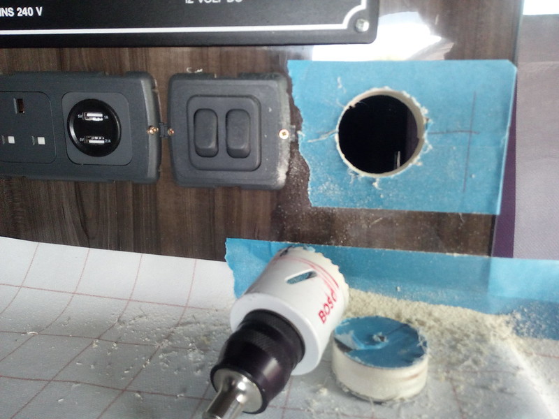
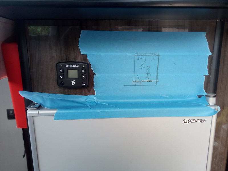
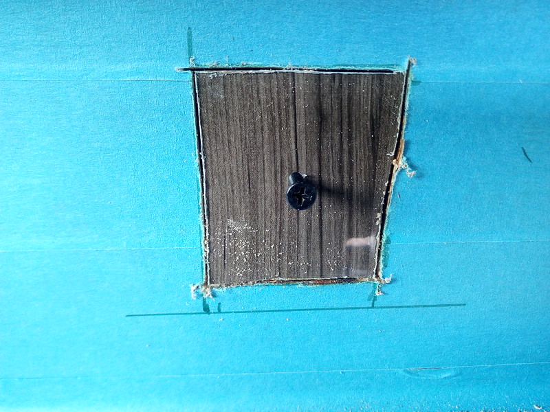
I drilled a pair of holes in the metal roof section that gets covered by the poptop

Solar Cable routing
by David, on Flickr
This could be a handy hint for some ... Put a strong magnet by the hole to be drilled and as the metal flakes and swarf comes off the bit, it goes onto the magnet and makes the cleanup a lot easier.

In the Poptop, I drilled holes - one for +ve and one for -ve - just aft of the cables coming out the junction box to drop the cables down and out of sight as quickly as possible. This is a closeup of one of the panels

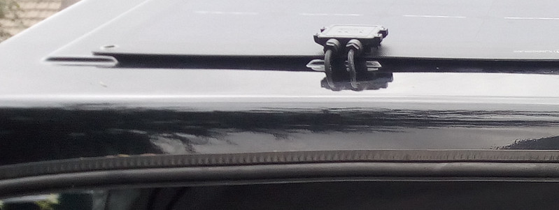
Cable Routing - PopTop
by David, on Flickr


Step 2: Fixing the Panels
The Lensun Panels I am fitting are defined as Semi-Flexible. They actually have a very rigid fibreglass backing on them and the makers recommend they be fixed securely (as opposed to be fixed to allow expansion in heat). The panels will just connect on the edges to raised ribs plus one in the centre. I wanted some more support in-between so got some acrylic strips cut to add inter-rib supports. This picture will show the fixings in place

Panel Underneath
by David, on Flickr
What you see in the photo above are strips of 3M VHB tape (taping these down rather than using Sikaflex or the like). The outer strips and the middle strip is VHB tape directly onto the rear of the panel. The 2nd and 4th strips are the 4mm thick clear Acrylic taped down to the panel and more strips applied to the other side of the support strips.
At the front there are some cross strips that are shaped infils between the Ribs - this prevents airflow underneath and eliminates any lift effect.


Step 3: Cabling Up
Two Panels going into one controller means combining the panels in either a Series or Parallel connection. But before that, we need to get the basic cabling in place. To cope with the rising roof I incorporated a bit of a loop effect to allow enough slack and movement whilst also trying to ensure the cables didn't escape out the side when the roof is lowered.
This is my layout outside

Solar Cable under Poptop
by David, on Flickr
So a pair of cables from the RH panel, another pair from the LH Panel and a last pair going out to the Controller.
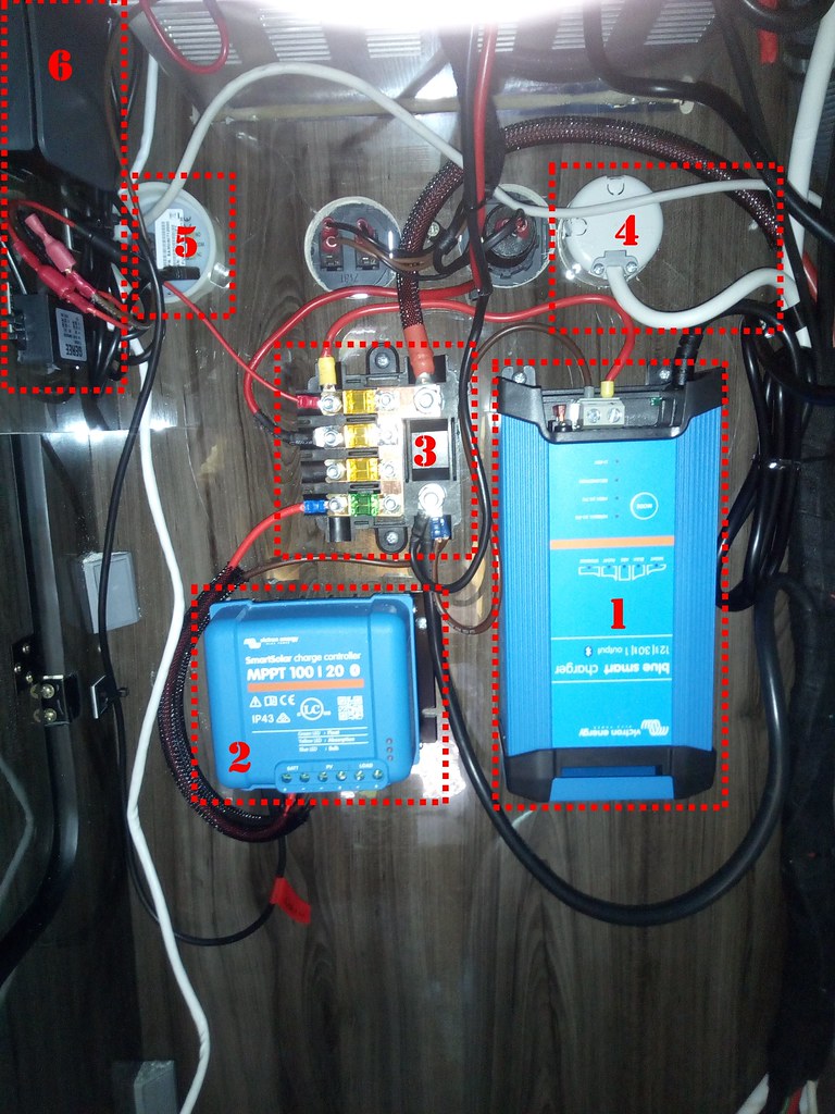
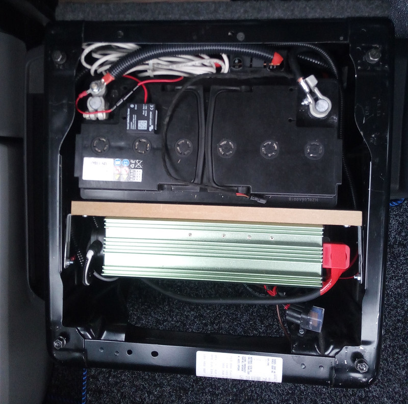
Inside the cables just route inside a cupboard out the way until they connect into the Victron MPPT Controller.

For the actual outside connections, I didn't use the typical MC4 connections found on Solar Panels (they had to get chopped off anyway to go through the holes) but used Wago lever connectors in an low-profile ABS box instead.
I set it up so the customer can change between Series (how I set it up now) and Parallel (preferred if you think there will be shade around)

Series Cabling

PV Cable - Series
by David, on Flickr
Here the Left Wago is the +ve and the Right Wago is the -ve. The +ve of Panel #1 goes to the Left +ve and goes to the controller; the -ve of Panel #2 goes to the Right -ve Wago and on to controller. The remaining -ve Panel #1 and +ve of Panel #3 gets connected together on the 3rd - middle - Wago

Parallel Cabling

PV Cable - Parallel
by David, on Flickr
To revert a Series to a Parallel setup here, it is dead simple! just eliminate the middle Wago and connect the +ve on that Wago to the Left (+ve) Wago and the -ve on the Centre Wago to the Right (-ve) Wago.

Using these Wagos make it very easy to alter the layouts as well as being very compact and secure, so ideal for this situation. The connectors themselves are rated for use at upto 300V and 20A so well within spec for this setup
P.S. The photos above are just to illustrate the connections - The actual cabling has all the insulation into the connectors!


Final Appearance

Panels on Roof
by David, on Flickr
The panels look pretty tidy, especially being virtually all black and mounted on a black gel poptop. The VHB on the roof is incredibly secure and you don't get ANY opportunity to adjust position (which can be a bit of a pain :( ).
The cables have enough flex so no strain and when the roof is dropped, no cables can be see other than a couple of centimetres by the panels.

This is the conclusion for this Camper Remodel. the Customer will be picking up his van at the end of the week after leaving it with me for just about a month. I have this as "Day 3" as this work could have been carried out in 3 days, but I probably spent around 5-6 full days on the work (I tend to work slowly but methodically)
 

wildebus

Forum Member
Top notch work, I guess with a sealed battery it doesn’t matter which way up it is.

Dave
Thanks.
Ref Battery, in the case of an AGM Battery that is indeed the case. Generally it is "any orientation except upside down". For a wet SLA (Sealed Lead Acid) you usually see the same thing but I personally would be a little wary about doing so (just hard to get the 'norm' out your head )
 

Glenn2605

Hi David,

Do you happen to have a full schematic of this install, it's exactly what I'm looking to do with our build and this would help greatly ?

Cheers,
Glenn
 

Glenn2605

I'm expecting the delivery of the AC charger this afternoon, this is an overhaul of the poor install that was there when we bought the camper - I did not realise you supplied kit as well but now I see the yellow link so will take a look at the bay store..
 

wildebus

Forum Member
I'm expecting the delivery of the AC charger this afternoon, this is an overhaul of the poor install that was there when we bought the camper - I did not realise you supplied kit as well but now I see the yellow link so will take a look at the bay store..
I can't send you a PM as you are a free member so that feature is not available to you (you might want to consider joining the forum as a member to get extra features?)
I just noticed my signature is out of date! I'll update it now :)
 

RAW

Forum Member
Dear @wildebus

What a fantastic and informative post

Just a question on Day 2 - whilst going through the Post, I notice you have put an isolator on the negative side by the Shunt for the BMV, is there also an isolator on the Positive side or have you just isolated Batteries via Negative ? Are there any issues isolating batteries via negative when in modern electrics the negative is often on the earth side ?
Day 2 - Leisure Electrics in the Cab

This T5 has a pair of single seats up front, so the space in the bases is where the batteries will be going, plus a few other bits ...


T5_Pass_Seat - Front Access
by David, on Flickr
Also added here, with access from the seat front is the cut-off switch (seen on the right).
Slightly unusually, this is cabled to work on the -ve cable rather than the +ve. It still works in exactly the same way though (y)

And at the rear, there is just the one thing for the user to care about - a fuse holder

---------------------------------

Cheers
Robert
 

wildebus

Forum Member
No isolation on the positive side. I did it on the negative because of the way the batteries were fitted and the wish to be able to get to the isolation switch directly without moving things (emergency requirement!).
No real problems using -ve instead of +ve. The only thing that will happen is if you have a BMV battery monitor, opening the switch will disconnect it. Usually the +ve on the BMV will be direct to the battery so that doesn't happen with a +ve isolation. This is a disadvantage but the switch is just for emergencies anyway so that is a very minor by-effect.
 

RAW

Forum Member
Nice one, was going to write a lengthy reply when this happened....
Screenshot 2019-09-26 at 15.00.23.png
 

Users who viewed this discussion (Total:0)

Top