My Overland Camperbus Conversion

wildebus

Forum Member
Inverter Overhead

Thought I would cover this seperately as is often wondered about - how much power the inverter uses when on but not being used?
The Multiplus, like most (all?) Victron Inverters have the option of setting in a energy saving mode. In the pheonix range, this is called ECO mode; In the Multiplus range, this is called AES mode but is essentially the same thing.
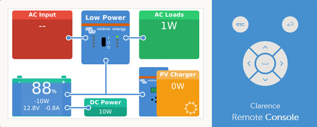
I have set up the Multiplus so it is in AES mode until it detects a load (e.g. Fridge kicking on) and then switches on while required. The screenshot below is my power consumption while it is in AES mode (reported as 'Low Power' by the Victron Monitoring system)

EnergySnapshot - CCGX (Inverter AES-Search)
by David, on Flickr
My System in total is drawing 10W - But bear in mind this is the ENTIRE Leisure Electrical System at this time, not just the inverter, so includes the Raspberry Pi and various little draws from the monitors and sensors as well.


So that concludes the 240V Side of the setup. Any questions or additional info wanted, just ask.

I will discuss the last - and possibly one of the most critical for long-term health - aspect of the Electrical setup next, that is the System Monitoring configuration.
 

Millie Master

Forum Member
This is an amazingly informative read Dave, you are to be complemented on your amazingly detailed and easy to follow drawings as well as your reasoning for and behind everything you are doing on the electrical side....... brilliant!

Hopefully admin or @Edina will agree and somehow make certain your efforts are made so that they are easy to find by anyone else looking for this kind of help with their cnversions.

Phil
 

wildebus

Forum Member
Electrics - Power Monitoring


Power Monitoring - A General View

There is a wide range of methods how to monitor the electrics in your Campervan or Motorhome - a writeup is available on my own website here.
As well as those examples, many top-range Motorhomes have some very advanced integrated electrical setups, but they tend to integrate the operation of the system (which is great) but rarely cover any kind of advance monitoring of the system.


Power Monitoring using the Victron System

Victron have a great reputation for both their products and the ability to monitor them individually and together via their Venus System and their Remote Management (VRM) Internet Portal.

I have a near-full Electrical Monitoring Setup based around the Victron Product Suite. With this setup I am monitor all aspects of the Electrical System remotely via the Internet. (I say 'near-full' because the one aspect I cannot directly separate is the Split Charge setup, but as that will only be active when I am in the vehicle and the engine is running, that part is not that critical)

This is a pictorial diagram of the setup in Clarence
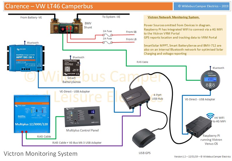
Clarence - Victron Monitoring Pictorial
by David, on Flickr
There is a Raspberry Pi microcomputer running Victrons Venus OS software, which is the management system heart (this is a low cost alternative to Victrons own Venus GX or Colour Control GX products); the various Victron devices connect to the Pi via special USB 'Dongles'; The GPS device provides Location and Speed Tracking and can be used as a Tracking and Alarm system as well.
The Raspberry Pi is set to read all the data the various devices provide on a minute by minute basis, saving that information and uploading via the integrated WiFi device linking to a 4G MiFi unit and onwards to the Victron VRM Portal which then provides the data in a graphical format for analysis and detailed records.
Some of the devices also have bluetooth connectivity to allow them to connect to a Smartphone App and to participate in their own Bluetooth Network.

So that is how it is cabled up and connected but what does it actually mean and do?


Bluetooth Networking

The first level of Victron Monitoring is using the Bluetooth App. This is the App showing the info for the MPPT Controller
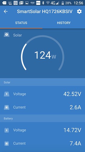
MPPT Controller
by David, on Flickr
The App allows the devices to be controlled as well as monitored in a similar way.

Using the VE Smart Networking, the devices talk to each other to improve the performance
In the screenshot below, it shows the Smart BatterySense, which is a device that connects directly to the Battery Bank and has a temperature sensor, sends info on Voltage and Temp to the MPPT Solar Controller and the BMV Monitor.
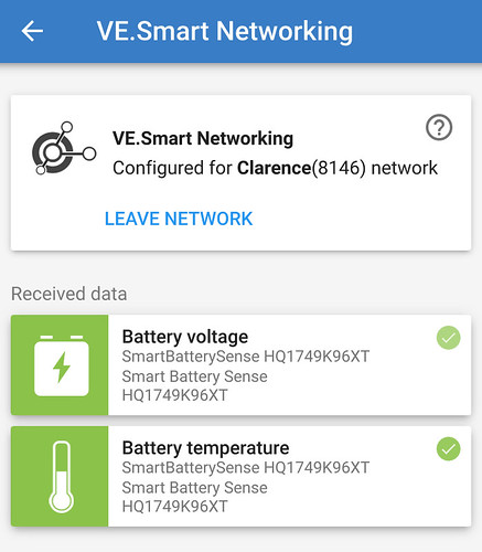
Victron Smart Network
by David, on Flickr
This allows the MPPT Controller to adapt its output voltage dynamically according to the battery temp and specific voltage (thereby bypassing any voltage drops in the cabling from Solar Controller to Battery); and the BMV to show the most accurate voltage possible to calculate the SOC more accurately.

Having Bluetooth connectivity is very useful and already extends the monitoring and control of a Motorhomes Electrical system beyond that of most factory installed systems.


Monitoring using Victron Venus GX

The next level is to integrate the devices using a Venus system.
Victrons main offering is the CCGX - Colour Control GX - Device, a specialist microcomputer with custom ports and a colour screen; and the Venus GX, a similar unit with some additional ports, but no screen. Victron also make their Venus OS open-source, which allows developers to port to other devices, such as the Raspberry Pi for example. I use the Raspberry Pi as my Venus device as it offers a much lower price point.

The CCGX lets you see the info directly on its built-in screen, but using a Web Browser, it is also possible to logon to the Venus OS device and see the same info on the screen. And as this is via a Web Browser, it is possible to do this from anywhere (unlike the Bluetooth method, which requires you to be pretty close).
This is an example of a CCGX display via a Browser
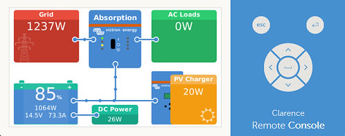
CCGX - MP3000 - Charger On (ABS)
by David, on Flickr

It is also possible to look at individual devices by selecting them
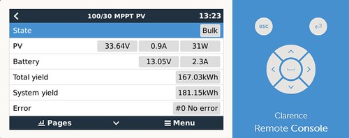
MPPT-Instant
by David, on Flickr

And drilling down further to get historical information
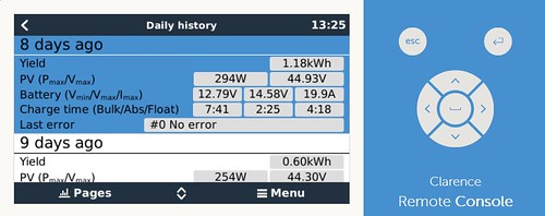
MPPT-History-Day8
by David, on Flickr

But more is possible ...


Monitoring using Victron VRM

Once you have an internet connection on your device running the Victron OS, it is possible to create a FREE account on the Victron VRM Portal (some demos available here) and log your data onto your own secure passworded installation to review and analyse the data in great detail.
The following are some examples of screenshots from the VRM to give a flavour of what can be viewed

Data viewable for a specific hour
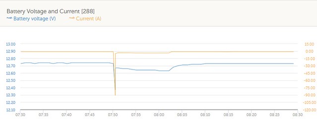
EnergySnapshot - V & C
by David, on Flickr

Or select a full 24 Hours maybe?
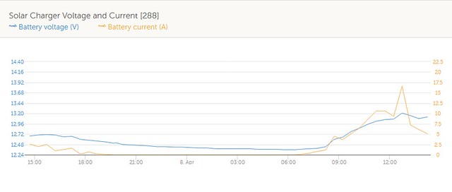
VRM-24H-Solar V & C
by David, on Flickr

And a view of consumption plus charging over a 24 hour period
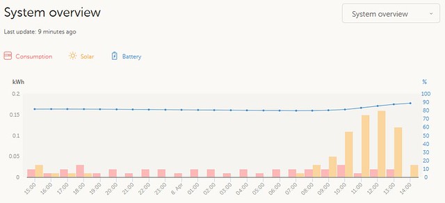
VRM-24H-System Overview
by David, on Flickr
This view can help determine if you need to adapt and improve any of your systems - storage or charging.

The above are just a few examples and the graph view can be as detailed as a 30 minute window going anywhere upto multiple years! All the data is downloadable and Victron say they will keep the data for at least 2 years at the detail level and 5 years for the overview. And all this is free for users of Victron kit.


Now the above could be overkill for many, but the thing is it available for those who do want this kind of info.


Conclusion

This completes the Electrical Setup of Clarence at this stage. As time goes on, things may change and evolve, but the essence will remain the same. Any questions on this, just shout :geek:
 

wildebus

Forum Member
An addendum to the Electrics in terms of Monitoring and Control ....

Went to IKEA and bought a new drawer front :) I have a 100mm high front piece on the sink cupboard where I blank off the bowl, and use it to fit various devices and switches. I needed to rework it after fitting the new Multiplus.

So it is looking like this now ...

Control Panel (Labelled)
by David, on Flickr (Labels for the photo ;) not actually there :) )

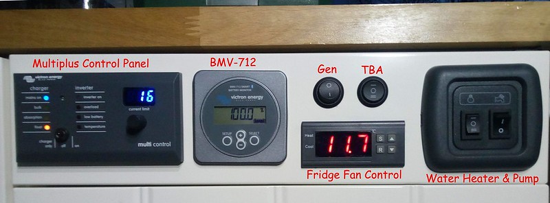
Left to right we have:
Victron Multiplus Control Panel. This is a remote version of the Multiplus Panel with extra flexibility. It adds the ability to change the maximum input current on the fly with the dial control (so in the photo above it is set at 16 Amps). This will be very handy when stopping off at a site with a low power hookup (It won't actually really affect how the electric inside can be used as when the EHU current is reduced, the Multiplus goes into 'Power Assist' mode and makes up the difference using the Inverter. So just end up using a bit of Battery Power and then extra Battery Charging afterwards).

Victron BMV-712. Battery Montitor that also has a relay system that can control the Water Heater.

Fridge Fan Control. There is a Temperature Probe attached to the Fridge Compressor and goes to this Controller. Once a certain temp is registered, the controller switches on its relay to power a small 12V fan aimed at the rear of the fridge.

Water Heater and Water Pump Switch Group.
Water Heater - The left switch is a 3-way switch for the Water Heater. In position I, the Water Heater is controlled by the BMV-712 relay which gets enabled depending on the battery SOC Level; In position II, the Water Heater bypasses the '712; and in postion 0 the Water Heater is off.
Water Pump - The right switch simply connects or disconnects +12V to the Shurflo pump.

'TBA' Switch. Basically this is not connected to anything at the moment and just a spare. (I think while it is spare I will use this to show a light to tell me when the Water Heater Control Box is getting power. Not essential, but might be a handy reminder as the heater can be a big battery hog if used off-grid).

'GEN' Switch. This is a switch that is connected to the Multiplus Remote Control Panel. When the switch is on, the Current set by the dial control is overridden by a value that has been previously set. I programmed this to 7 Amps to suit my P2200 Generator which has a maximum running power of 1700W to ensure it will not go into Overload.
When the switch is on, the display changes to tell you it is in the Generator override mode

Control Panel (Gen)
by David, on Flickr


I haven't actually covered the Galley Kitchen yet either, so that will be next post for this build thread.
 
Last edited:

GEOFF

WOW - I have just read (but not understood the electrickery side) this build log from start to finish. A great and very interesting story. Thanks for posting and well done. A much impressed Geoff.
 

Lord Lucan

Excellent work, excellent post.

I dare’nt post any of my conversion now 🙈
 

wildebus

Forum Member
Updating The Battery Bank

When I fitted out Clarence the LT Camperbus, I built a battery box to suit 4 x 110Ah AGM Batteries, specifically from Leoch.

I had the opportunity in the last month to get some bigger batteries at a good price off Phil (Admin) , so bit the bullet and picked them up last weekend and fitted them this week (y)

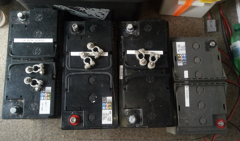
These were the batteries I was running and took out - the Xtreme XR-1750 model

Xtreme XR-1750 Batteries
by David, on Flickr
These have been excellent batteries but you can never have too much power, can you?! :p

And the battery box I built for them

1. Old Batteries Out
by David, on Flickr


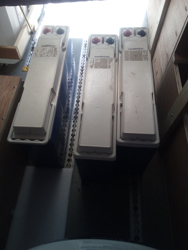
These are the new Batteries.

2. New Batteries to be fitted
by David, on Flickr
They are NorthStar NSB 210FT Blue+ Batteries, rated at 214Ah each at the C20 Rating at a temp of 25 Celcius - check out the data overload below!

NSB210FT-25C Discharge Table
by David, on Flickr
I've marked the appropriate C20 value for the recommended discharge voltage in orange (I do like a item where there is lots and lots of information provided. It tends to show a well designed and researched product :geek: :geek: :geek:)


Annoyingly, the width of these batteries side by side is around 23mm wider then the battery box, so I have to modify the box
I cut the outer side off to make the extra room

3. Battery Box Side Removed
by David, on Flickr
Having the side off is actually quite handy as well as it allows me to manhandle the batteries into the box without having to lift up and over a side panel, which would be very tricky as the bed slats are above the batteries and so had to get good leverage, plus these batteries are rather heavy at around 11 Stone each :eek:


So the new batteries are now in place and I have a strap keeping them together

4. New Batteries in Place
by David, on Flickr


Made up a new side panel with little filler to provide the neccessary offset and added some silver bubblefoil to keep everything from moving within the box. Also a short panel the other side was added.

5. Replacement Side Fitted
by David, on Flickr


Fitted some top covers to enclose the batteries for protection. I used separate pieces to use up spare plywood I had and also allowed me to have the terminals available to secure cables easily.

6. New Top Cover Panels Fitted
by David, on Flickr
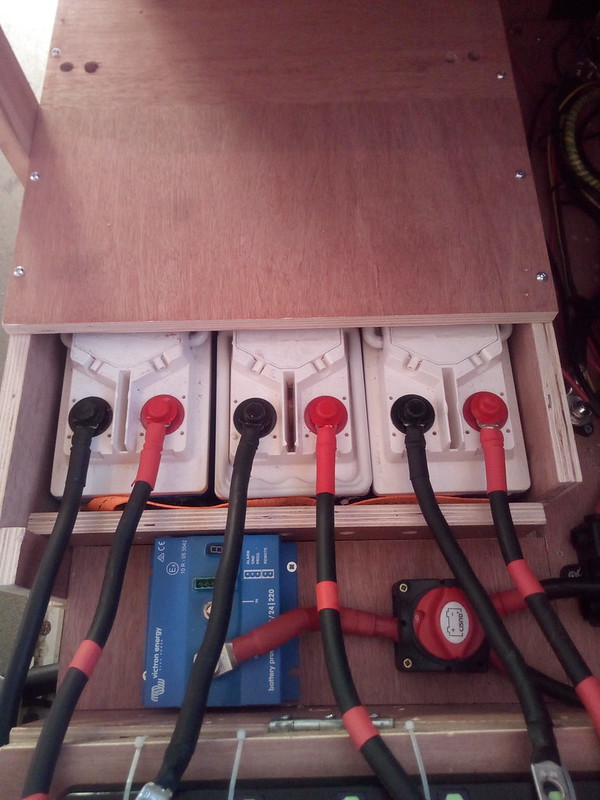
The new layout allowed me to resposition the Master On/Off Switch in a neater location and I also fitted a Victron Battery Protect module. To be honest, I don't really need this but I thought it would be interesting to run one, especially as I have some very high current devices.


Cables installed. I'm using 50mm Cables here for minimal voltage drop (If I were doing this as a brand new install I would probably have made some 70mm cables, but I could reuse the 50mm from the old install and 50mm is definately well within spec anyway)

7. Power Cables Fitted
by David, on Flickr
On the previous battery installation I fitted battery interconnect cables, arranged to balance the loads equally across all the batteries. On this installation I decided to have the batteries individually cabled and running to common busbars to then feed to the system, using the same product as Phil did on his 4 battery Lithium Battery installation.


And the cables heading to those busbars and also to the Battery Protect

8. Cables routed to Lynx Management
by David, on Flickr


The Busbars were actually within a Victron Lynx Distribution Box.

9. Fuses Fitted
by David, on Flickr
At the bottom of the Unit is the GROUND Busbar and where all the Battery Grounds were secured. This unit was slightly modified on the +12V Busbar upper level to allow each Battery to be individually fused (I used 125A Megafuses) and then the output (to the left) goes out (via a 500A Megafuse) to the Battery Protect unit.
The Ground outlet heads to the 500A Victron BMV Shunt and then to the Ground distribution post.
As mentioned, the Battery cables into the Lynx Busbar are 50mm, but the cables out to the system are all 70mm cables in order to cope with currents hitting 200A


And with all covers fitted

10. All Complete
by David, on Flickr
The little fusebox on the right are for low power system monitoring supplies which I don't want to go off if I turn the master On/Off switch to off. These are the power to the BMV Monitor, the Raspberry Pi, Smart Battery Sense power and Multiplus Battery Voltage input, plus the Garage Space lights so I can see what it happening if I need to work on the system at night time.


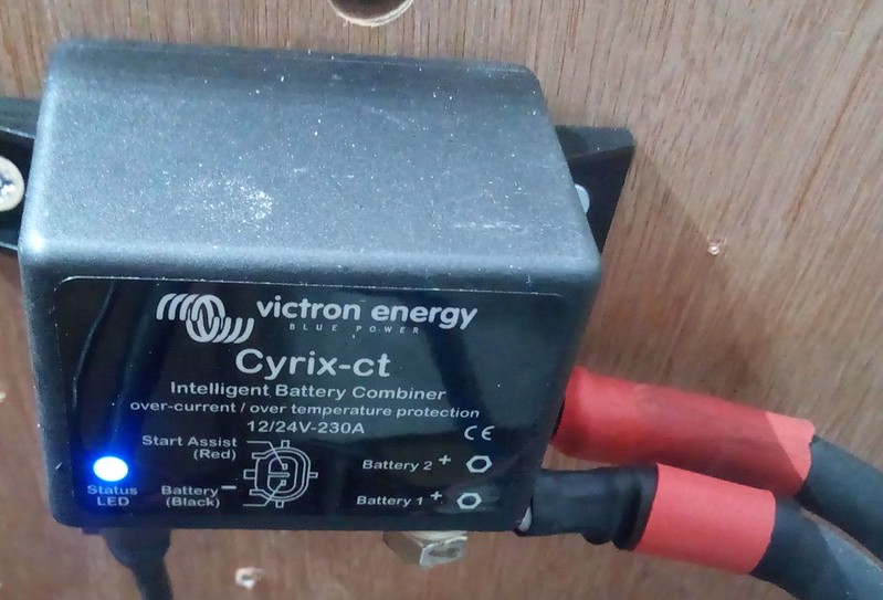
Also installed is an uprated VSR from Phil. I had previously upgraded the Split-Charge cable from 16mm to 35mm in readiness and I could just swap out the old 140A basic VSR for a 230A Victron Cyrix-CT Combiner.

11. Cyrix-CT 230A
by David, on Flickr


These new batteries have a total capacity of 630Ah (at the C20 rating) compared to the original banks 380Ah (at C20) so a fair increase.
I carefully went through the spec sheets of the batteries to check the charging levels and setup the Charger accordingly.
These Northstar NSB batteries have a lower charge voltage then the typical battery at just 14.1V, with a float of 13.62V. 14.1V sounds quite low but that is what the spec sheets says, so that is what I am using.

MP3000-Charger
by David, on Flickr
I also changed the MPPT Controller parameters to match as well

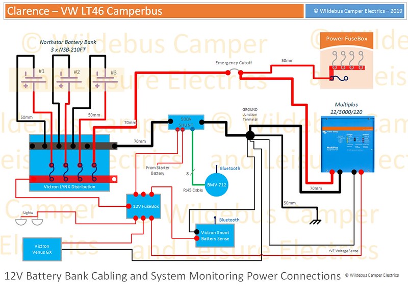
Finally, updated my wiring diagram to match the new setup...
Clarence - 12V Power Distribution by David, on Flickr
 
Last edited:

Lord Lucan

Amazing works....... things you have to do when the wife must have her straighteners 😳
 

wildebus

Forum Member
I decided to add some additional features to the Victron monitoring setup :)

I changed the Raspberry Pi to a Victron Venus GX Device to compare the two.
The actual Venus GX unit has some extra digital inputs built in which can be used for various types of inputs, and I took advantage of this ...

Devices
by David, on Flickr

Added the following:
"Car Alarm" - When the Car Alarm is enabled, if it goes off, as well as setting off the siren, the same output is routed to the Venus GX on a specific input. If this input goes high, an alarm is emailed to me so I know something is awry.

"Door Alarm"
- If a door is opened, this input gets set as 'Open'. I can set an alarm for this event and have a warning emailed to me in real time.

"Water Heater" - This is just a flag to tell me the Electric Water Heater control is getting power. Not a massive need for this TBH, but it could be useful to know if I leave the Heater switched on when I will not be using the Camper for a while. So a handy check/reminder function.

"Kerosene Heater Fuel Use" - This I think could be very handy. I have a separate fuel tank dedicated to the Space/Night Heater which has a capacity of 10L. These heaters use a fuel pump to deliver a metered amount of fuel on every pulse they receive. This monitor input counts the pulses and counts up the amount of fluid (i.e. Kerosene in this case) that is getting pumped. This replaces the need to have a fuel gauge fitted to the tank or to visually check it (y). The quantities are selectable in Litres, Cubic Metres, or Gallons, which are all too large really for my needs, so I am treating the Litres Entry as being ml and have set the quantity per pulse accordingly, so if it reached 10,000L, for example, it would have emptied the tank. I can set an alarm when the fuel use hits a selected amount (probably go for something like 8000) I will get an email which will promt me to refill the tank in plenty of time :cool:.

This kind of functionality expands the functionality of the Victron kit beyond detailed Electrical Power Info into useful general Motorhome features. I am contemplating adding a Grey Water tank sensor as well (the Venus GX has separate tank inputs as well).
 

wildebus

Forum Member
Went to Busfest last weekend (Busfest is billed at the "Worlds Biggest VW Bus Show") :)

Had a wander around and decided to get some step carpets from Harrison Trim Supplies (a major name in cab and custom carpets in the VW Camper world).
They don't have off-the-shelf step carpets for the VW LT, so I left them with the offcuts I had cut to size and was using currently to use as templates.
This is what I had:
IMG_20190913_155853 by David, on Flickr
Functional but boring.

Now replaced with this:
IMG_20190913_155935 by David, on Flickr

I got the Sliding Door Step done as well:
IMG_20190913_161049 by David, on Flickr

Bit of a surprise, but when they send the new step carpets to me, they also sent back the offcut templates, but not before whipping the edges first :)
IMG_20190913_161113 by David, on Flickr

Ordered on Sunday, Delivered to me today (5 days later) by DPD - cost £8. Well Happy with that :D
 

Andypandy

Hi. I'm new to this site . Found your articles here mega interesting. I've just bought a LT46 minibus and will be going down some of your road with the conversion.
Your peice about the seats will be copied to start with . Mine is a petrol /Lpg model so no probs with gas for hob etc as it has 3 underside tanks . But I'm going to have to make a bracket to mount spare wheel on rear door .
Anyway would you be so kind as to post some pictures of the inside like living area .
Ps. Love the photovoltaic panels on roof.
Probably copy that as well.
Cheers and thanks . Andy .
 

wildebus

Forum Member
Hi. I'm new to this site . Found your articles here mega interesting. I've just bought a LT46 minibus and will be going down some of your road with the conversion.
Your peice about the seats will be copied to start with . Mine is a petrol /Lpg model so no probs with gas for hob etc as it has 3 underside tanks . But I'm going to have to make a bracket to mount spare wheel on rear door .
Anyway would you be so kind as to post some pictures of the inside like living area .
Ps. Love the photovoltaic panels on roof.
Probably copy that as well.
Cheers and thanks . Andy .
Hi Andy,
Thanks for the reply and glad you found it interesting. There may be more useful detail on my website here - https://www.wildebus.com/clarence/ . If there is anything specific, please just drop me a PM and I will see if I can help :)

Like all conversions, there is always still stuff to do but generally everything has worked pretty well as expected (which makes a change!).
The standard minibus ceiling panels are quite wasteful in space, so a main thing I want to do still is to remove those and fit slimline high lockers and a ceiling panel.
 

wildebus

Forum Member
There will be no more updates from me for Clarence as he has now gone to a new home.

The good news is that the new owner is a Joiner so he will be able to make the interior much nicer than my own efforts suceeded in doing whilst retaining the great electrics setup, so an ideal new home I think.
 

Users who viewed this discussion (Total:0)

Top