HTF's campervan build

HTF

Forum Member
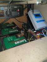
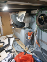
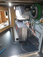
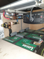
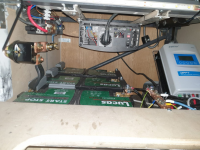
The rest of the electrical equipment is located under the back seat. I have 3 AGM 12v 95 aHr batteries running in parallel with space for a fourth. On top is a 1500 W/2000 W peak 230 v 50Hz pure sine wave inverter and on the right, the 40 A MPPT solar controller. There is an emergency manual cut off switch in case anything bad should happen but I think there are more than enough fuses to protect the wiring.
When I press the power up button, a certain sequence must happen to avoid damages. The PLC is powered up and the battery voltage measured and if ok, the sequence begins. The main power relay is energized first. It's important that the solar charger is connected to the batteries before the solar panel so, it's relay does this and then the solar, the pumps in sequence, the fridge and so on with the inverter connected last. All systems can be individually activated and deactivated by the PLC control panel. The PLC also monitors the van door lock/unlock condition and I'm able to do this remotely through my phone. When the van is started, the alternator voltage is checked and if necessary, the camper batteries are also connected to the alternator.
1695496302691.png1695496321116.png1695496335272.png1695496347306.png
 

HTF

Forum Member
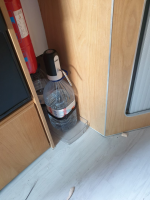
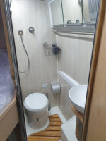
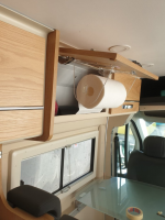
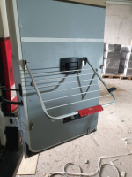
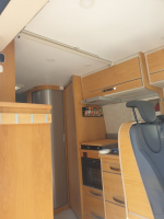
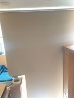
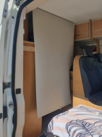
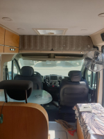
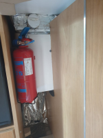
I have mentioned before that I like to have a proper space for everything, when you need it it's easy to reach. We buy 5 liter jugs of water for cooking and drinking so, a little battery powered pump makes it easy to pour. I also have a ABF fire extinguisher right behind the kitchen counter, a place for the small vacuum cleaner to charge, dust pan and broom, shower proof toilet paper holder :cool:, paper towel roll in arm's reach, fold out towel rack by the external shower, picnic table and chairs and so on. Once again IKEA was the source of the privacy curtain and I cut one of those thick felt office sound dampers also from IKEA to cover the shelf above the front compartment.

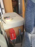
The fan that can be seen behind the passenger seat is a 230 V unit connected to a smart plug and can be switched on and off through the Internet. The inverter is always connected so, 230 V is always available.

1695496601228.png1695496611731.png1695496624506.png1695496633132.png1695496640842.png1695496651290.png1695496660185.png1695496671297.png1695496679201.png1695496688035.png1695496698639.png
 

HTF

Forum Member
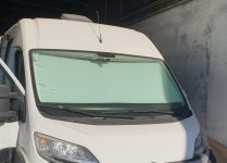
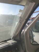
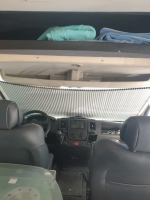
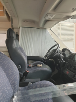
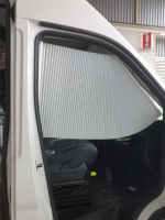
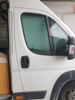
Looking at the prices they charge for those built in blinds for the font windows, I had to look elsewhere. Once again I found some automatic ones at IKEA so, a little adapting and they fit very well.

1695496838491.png1695496848523.png1695496856184.png1695496864130.png1695496871754.png1695496879083.png
 

HTF

Forum Member
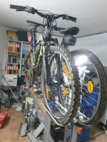
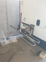
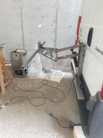
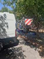
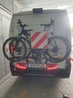
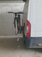
Initially I intended to store the 2 bicycles we use in the "garage" but, the front wheels would have to be removed and some valuable storage space would be occupied so, I decided they would go outside.
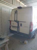
Hanging them on the fragile doors was out of the question so, I replaced the flimsy bended sheet metal bumper with a reinforced rectangular piece of section strong enough to mount a tow hitch. Looking at the options for hitch mounted bike racks, they would be in the way of the back doors and ride low covering the rear lights and licence plate.
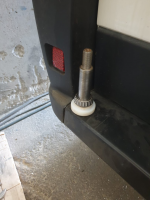
Back to the drawing board I went and decided on building something that would swivel like a 4x4 spare tyre. Had a steel shaft turned and mounted 2 taper bearings on a swing support. I decided to make a different style support that would securely hold the bike and make it difficult to be stolen. Since I have access to a CNC plasma cutter at work, I gave it a little style and with the aid of an electric actuator, I could lower the bikes to load and unload and then move them out of the way.

1695498384405.png1695498392633.png1695498400462.png1695498409263.png1695498420643.png1695498450364.png

https://flic.kr/p/2p3mJsE
 

HTF

Forum Member
The first trip went well and since I can connect the rearview camera while driving, I could check every now and then how things were. Although everything was in the same place after the more than 1200 km journey, on some bumpy roads the bikes would swing a little and I didn't want to risk some overzealous Policeman stopping me and saying that the rack might break so, I removed the actuator and arms and designed a small bumper with rear lights and licence plate. I didn't want to have physical connection to the light so a special contact system was designed.

1695498739981.png1695498751135.png1695498759834.png1695498771493.png
 

HTF

Forum Member
Near the end of that first trip I started to see a little water drip from the roof down the side of the van. A quick inspection revealed that the solar panel sprung a leak o_O. The "so called" special contact glue from 3M didn't resist the heat and let go and possibly the vibration must have done something to the piping interface. I't wasn't a big leak but I didn't want to risk so, I deactivated the solar circulation pump and the few days left of the vacation meant cold showers but, is was summer :D

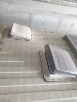
Back at headquarters and after a close inspection, I found that the problem was worse than I thought and drastic measures had to be taken. I felt that anything I would glue to that EVA material from the inside of the solar panel would eventually come lose so another solution came up. Since I wasn't going to put a rooftop air conditioner over the back skylight anymore, I had some space so, if a "Hybrid Solar Panel" didn't work, I would get a thermal one :cool:

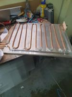
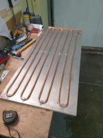
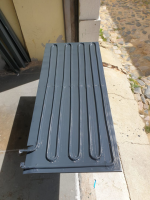
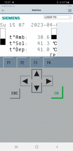
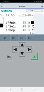
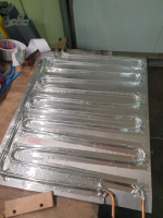
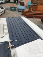
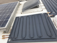
To maximize the area available, 2 separate panels would be required so, I bought 15 meters of copper pipe, a little plywood and still had some of that (you guessed it :D) aircraft aluminium. Glued and screwed the aluminium to the plywood for back insulation, grabbed the pipe bender and made some zigzag coils of copper pipe. Some thermal tape was stuck between the tubing and the aluminium and some clamps were added. 3 layers of thick aluminium tape was used to conduct the heat from the aluminium back panel to the copper pipe. A few coats of high temperature mat black finish it off (fresh paint looks glossy ;)) This meant a few more rivet nuts and sealant on the roof and redirection of the pipes. It worked better than expected. The temperature readings show the (tºAmb) ambient, (tºSol) return water temperature just before it enters the tank and (tºDep) the tank temperature. The readings were taken on the beginning of April after 4 hours of sun exposure.
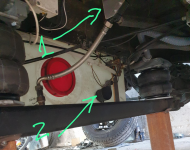
You can see in the photo, the tank before insulation, 1- circulation pump and 2- backup water heater resistor.
1695499971225.png1695499978345.png1695499985219.png1695499992380.png1695499998405.png1695500012383.png1695500020489.png1695500041112.png1695500050036.png1695500066551.png
 

HTF

Forum Member
From the beginning I planned an air conditioner for the sleeping area but after looking at the prices, I gave up. I wasn't going to pay around 2000€ for a rooftop air conditioner that must run on "shore" 230V or special inverter. I like to go anywhere and don't condition my stay on the availability of 230 Vac so, an alternative had to be found.
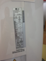
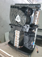
Looking around I found a nice little Inverter Drive portable air conditioner from LG with 8500 Btu/h which would only draw a maximum of 910 W and this is a variable power draw since the inverter will only run the compressor needed speed so, I had the power for it. Ordered it online for 450€ and when it arrived, it was a little bigger than I expected. This meant that I had to find room in the garage and a connection for the hot air to the outside.
Found some space above the rear wheel but the 200 liter tank was in the way. Had already noted that the visits to the service station in my case is regulated by the cassette capacity and not water so, I could reduce the main water tank to half the size. This meant that I would have a long and low space and not the short high space needed :oops:.
The aircon had to go through some surgery :whistle:

Tested everything was working before removing the covers and compromise the warranty and then, the warranty went out the doo

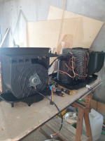
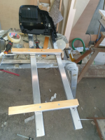
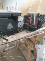
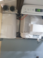
After a close inspection I found that would be very easy to transform it from skinny tall to shorty long. The top evaporator (cold) side was separated from the bottom condenser (hot) and the fans were totally enclosed so, I made a sled and carefully positioned the two parts without damaging the pipes. I was prepared to cut them and refill the gas but it wasn't necessary 🥳

These units come with a flexible pipe to blow the hot air to the outside. Air from the inside is blown through the condenser to cool it and blown outside. In a big room, this isn't much of an issue but in a small camper, this would mean that a vacuum would have the inside air replaced by hot outside through, probably the van's vent from the outside.

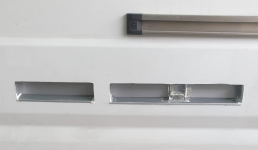
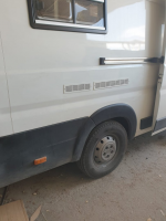
2 grills to the outside were opened on the side and some water protection channels were added. The cold air generated was enclosed in a "box" where the conduits route the air through 2 vents over the bed and below the bed trim to the cabin. The hot air output was in a awkward position so a little enclosure was made.

As a bonus, the aircon is online so I can monitor the ambient temperature and be switched on when we leave the beach and arrive to a cool van :cool:

1695500629997.png1695500644847.png1695500653209.png1695500723112.png1695500733630.png1695500741842.png1695500750791.png1695500759460.png1695500768959.png1695500777388.png1695500787591.png1695500795869.png1695500811443.png
 

HTF

Forum Member
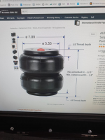
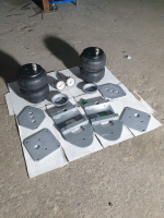
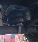
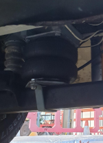
The "final" job was the "Spring helper". Being close to the maximum weight of 3500 kg, the back suspension was riding on the rubber bump stops so, I decided to install some air springs just to help the original ones. Looking around I could only find kits at prices I wasn't willing to pay. Tried to find just the airbags around here, only big truck types could be found so, I tried Amazon.com and voilá, a pair of airbags for the Ford F150 for less than 200€ including import duties and taxes.
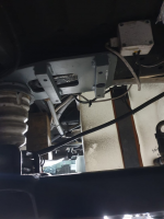
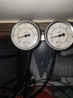
In less than a week they arrived and it was time to make some adapter plates. Fortunately there was a M14 threaded insert next to the one on the rubber bump stop and I could use these two holes to mount the top adapter plate. The airbags also come with threaded inserts so a square plate was made to bolt these and 2 standoffs were welded to the top adapter plate to allow space for the air fitting. On the bottom a saddle clamp was used to mount to the axle. The bags are individually connected to a block of aluminium drilled for a pair of gauges (these have a 30 Bar scale but they are robust and being recycled, I could not get a better price 🙂) and a pair tyre style filling valves. I can fill them individually with my small compressor and stay that way. Around 1,90 bar is all its needed to ease the weight on the mainsprings. The van has already gone through an MOT inspection and the guy said that it was ok. If there were any issues about it, I could remove it before going there.

1695501471644.png1695501479563.png1695501486188.png1695501493780.png1695501501298.png1695501508407.png
 

HTF

Forum Member
This concludes the build :D. There is never a "final" job as I said before because, there is always something that can be improved or added.

I hope you folks liked and feel free to comment. It was my pleasure to share a few photos of my build.
 

st3v3

Forum Member
What is the current draw when the van is just sat with all of the systems on but not being used? PLC/inverter/router etc. All that stuff, what does it add up to?
 

HTF

Forum Member
What is the current draw when the van is just sat with all of the systems on but not being used? PLC/inverter/router etc. All that stuff, what does it add up to?
Everything on and idle, less than 25W. This draw would empty the batteries in a little over 5 days if there were no charge at all. The fridge alone, an average of 12w/h. Haven't had any problems with power shortage, yet.

When the van is in storage, the batteries are completely disconnected from load with the exception of the battery monitor Coulomb Meter that draws less than 4,5 mA. This way it doesn't lose its memory count.
 

HTF

Forum Member
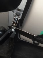
As a measure of safety, I installed some safety blocking of the front doors on the inside. Bolted a traditional car pilar door "latch receiver" and made some plasma cut hooks that clamp the doors shut by leveraging on the lower seat belt support. A winged bolt tightens the clamp. 20230817_162527.jpg
 

Millie Master

Forum Member
Have you by any chance loaded all the tanks (water. foul water, grey water, diesel, gas) to the brim, loaded your normal holiday gear, your food and you and your passengers into the van and then gone onto a weighbridge? Is the total GVW still within limits or do you need to replate?

Phil
 

HTF

Forum Member
Have you by any chance loaded all the tanks (water. foul water, grey water, diesel, gas) to the brim, loaded your normal holiday gear, your food and you and your passengers into the van and then gone onto a weighbridge? Is the total GVW still within limits or do you need to replate?

Phil
Hi.
The van unloaded and with a 100kg driver is still under the 3500kg limit otherwise it would not pass the MOT inspection every year. Loaded it will go a little overweight, unfortunately although the maximum permitted weight per axle which is 2100 kg front and 2400 kg on the back is well within the limits.

Unfortunately replating in Portugal is no so easy but I'm, trying. In Portugal and the rest of the EU normal B drivers licence allows campervans up to 4250 kg to be driven but the problem is with the DMV which needs an authorization from the factory to change the GVW.

On the van's manual, all the Jumper/Relay models appear and my van has a model with a GVW of 4005 kg which is the only thing that changes from the 3500 kg model as everything else is the same such as the maximum weight per axle of 2100 and 2400 kg which leads me to believe that this was done for the professional van builders. I've written to the factory asking for this authorization bu still waiting for a reply.

In the meanwhile, I drive the van as is hoping that I don't get pulled over to be weighed. If you look at the van it doesn't look overweight ;)


Jumper.jpeg
 

Pudsey Bear

Forum Member
Back to the build. This video has been posted on the Show us your van thread but I think it should also be here. Here the build is almost complete and was going for the DMV inspection to get the vehicle reclassified as a campervan :) A step by step explanation will be posted next.

https://flic.kr/p/2p2jrXn
Wow! if you built that I am seriously impressed, you should do it for a living if you're not already.
 

HTF

Forum Member
Thanks for the comment. I have a big difficulty repeating things. I like to innovate and challenge myself. I've proved myself that I could do something to be proud and share without fear of saying "I made that". I'm looking for a new challenge :)
 

HappyChimp

Forum Member
Old thread but its new to me! really informative and some great idea's I will be studying it over the next few months when I start my relay build. Thanks for sharing :)
 

MarkJ

Forum Member
with the aid of an electric actuator
Damn. Wish I'd thought of that. My original plan was to have our electric bike suspended in the garage high up at ceiling level. I did all the support stuff and got it working but we decided the faff was just too much and abandoned that plan. Wish I'd thought of motorising it!
 

HTF

Forum Member
Changed my battery bank from 3 automotive Lucas start/stop AGM 95 ah batteries to 3 AGM deep cycle 125 ah. Not a big difference in size and weight but quite a difference in capacity. Now I can run my compressor refrigerator and separate 20 L freezer without worries. I don't like being dependent on "shore" power.
 

Users who viewed this discussion (Total:0)

Top