Tech Neck Hot Water System

wildebus

Forum Member
What's "Tech Neck"? Well, it is like a Red Neck setup but using Technology :)

I was going to install a Eberspacher Handiwash system in my Campervan, but that requires a wall to mount it on and I will not have any walls in my build - at least not in build 1.0

I do want some hot water though. Currently I just boil a kettle on the hob and to be fair that works pretty well (a 2kW induction hob is VERY fast!). But I also think I should be maximising the solar power which is going to waste when the batteries are full.
Pretty common stuff, but the Tech Neck bit comes in as I don't want to splash out any real money to do this :(

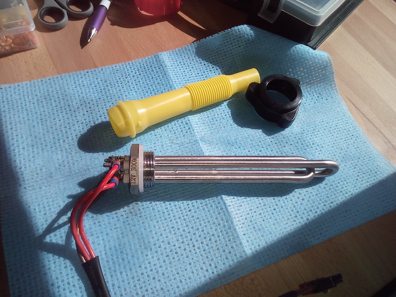
So 300W immersion heater element bought from Amazon - Aiicioo 12v 300w Heating Element DC Immersion Heater with BSP Thread Submersible Heater for Solar Energy or Wind Turbine: Amazon.co.uk: DIY & Tools

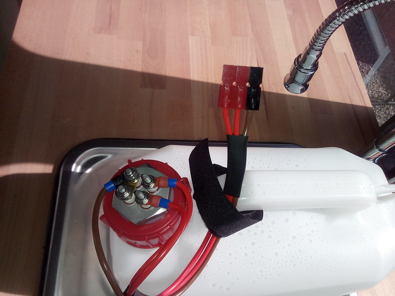
Made a hole in the cap of a spare water container:

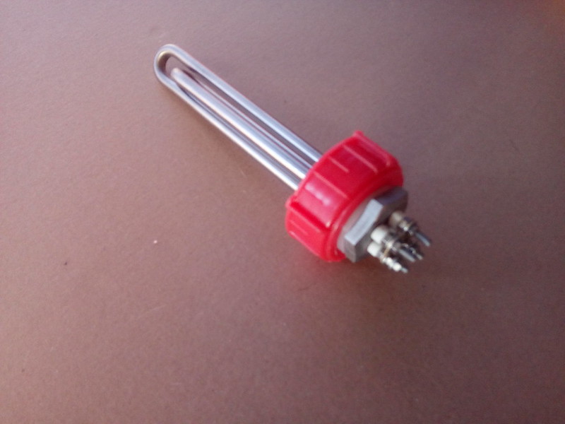
Heater in Cap
by David, on Flickr

Filled up the container (just a 10L one) in the sink

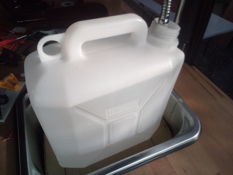
Hot Water Container
by David, on Flickr
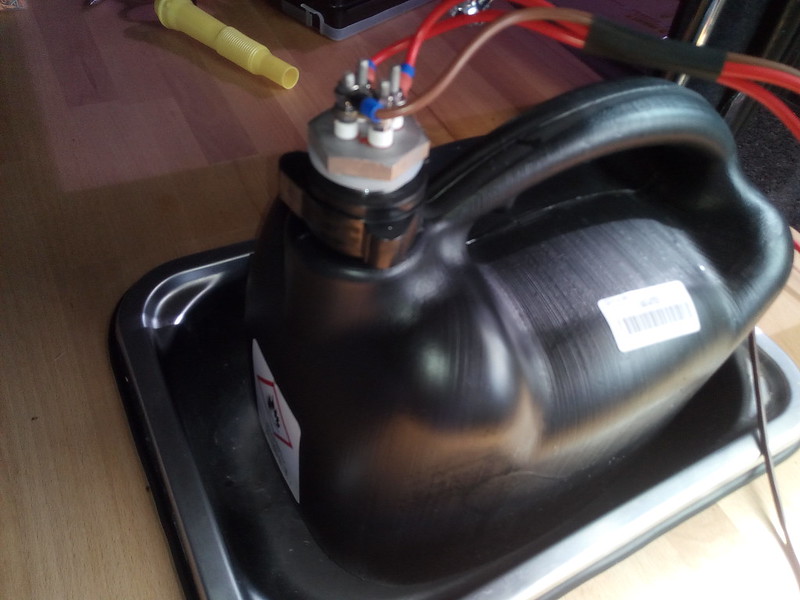
And fitted cap

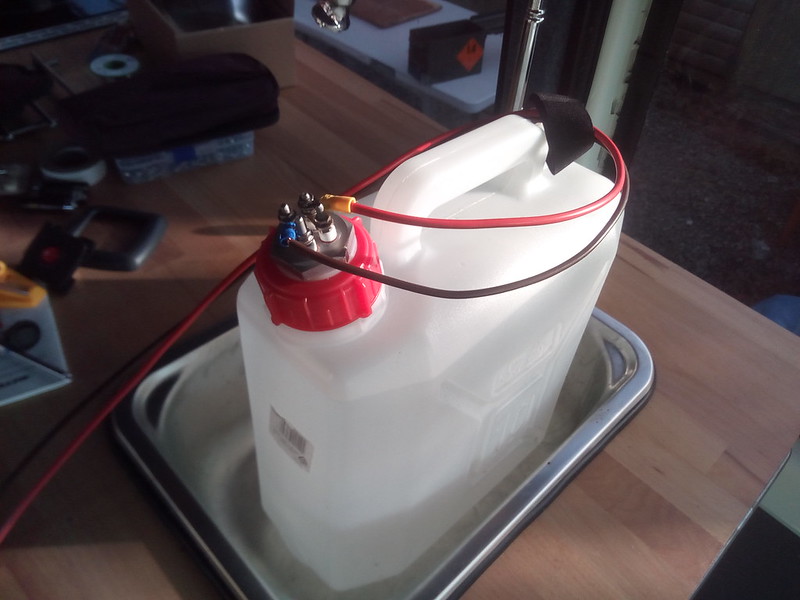
Hot Water!?
by David, on Flickr

The angle of the heater is fine and the element is not touching the sides at all. Of course how well the container stands upto the heat is another question, and one reason why I am leaving this in the sink for the testing ;)
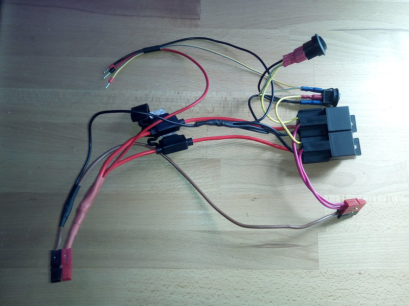
I will also fit the wiring onto a quick-disconnect so it will be easy to remove the container cap. Using an external 30A relay, protected with a fuse and with 4mm Stranded Cable to supply the power to the heater element,


Now the heating ....
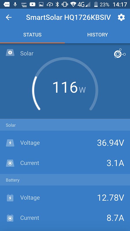
One option that some people use is the LOAD terminals on their Solar Controller. Mine is a Victron 100/30 MPPT Controller and only has a virtual LOAD terminal - and I cannot use those as they are used by a USB connection to the Raspberry Pi running Venus GX s/w.
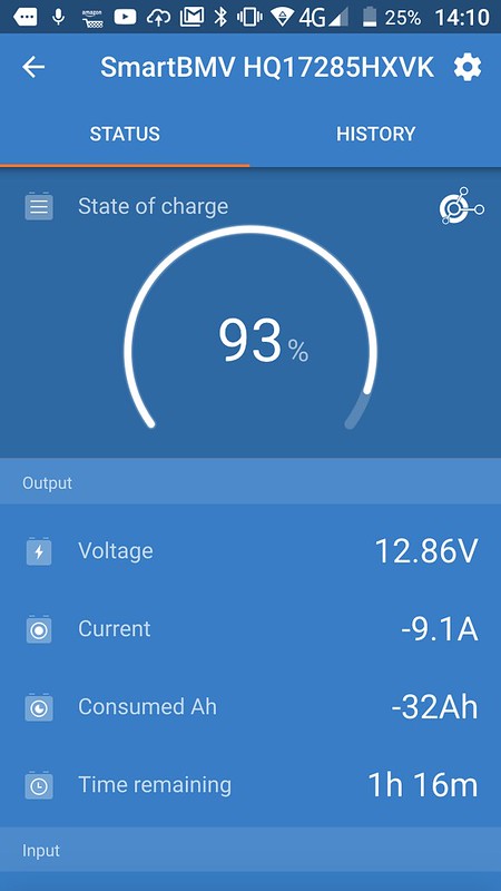
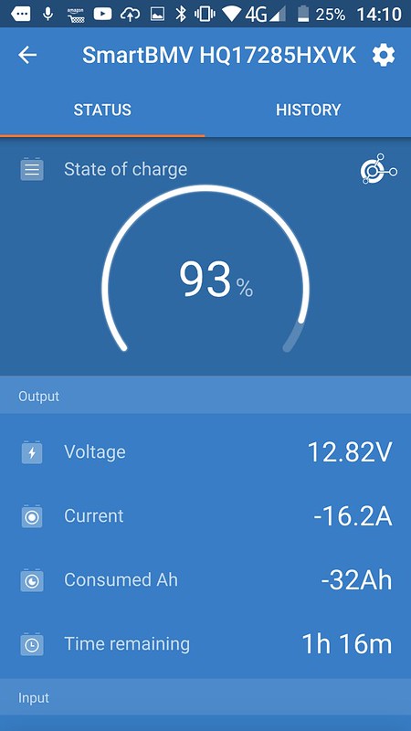
However, the Victron BMV-712 I have has a configurable Relay which I should be able to utilize :)

BMV-712 Relay Setup
by David, on Flickr

I used the SOC (state of charge) setting to control the relay action. This is primarily designed to be used to kick on a generator when the SOC drops to a certain figure, but of course, I want to turn on the relay when the SOC rises to a certain figure - the opposite action! Luckily Victron provide an "invert relay" option to reverse the standard operation, so this was turned on.
After a bit of testing and playing around to make sure the relay was doing what it was meant to, set it up with the following parameters ..

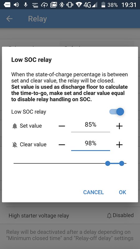
SOC Settings
by David, on Flickr
The description of how it works in the screenshot about is slightly simplified but in essence right.
So when the relay is off, when the SOC hits over 98%, the relay turns on. It then stays on until the SOC drops below 85%. These numbers I kind of plucked out the air to test things out - obviously fine tuning will be required to get them right.

How long will it take to heat up the water? I used this on-line calculator - http://processheatingservices.com/water-heating-time-calculator/ - and it told me to raise the temp of 9L of water by 50C using a 300W heater should take 104 minutes.
the water in the container was around 25C and the relay clicked on at 19:30, at which time I went in for some supper :)
Came out at 21:00 to check the water and it was a very hot 85C! - so actually just 90 minutes to heat (maybe I only had 8L of water in the container?).
The SOC had dropped from 99.2% to 89.0% - so 10% of the battery used in this time. There was some solar coming in, but of course I had other draws as well, and those two pretty well cancelled each other out.
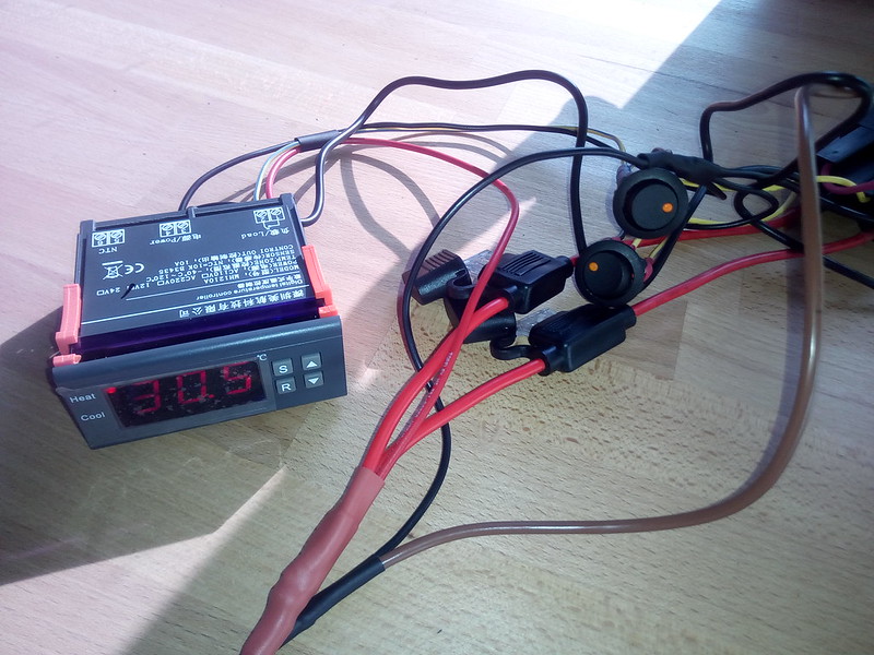
So it looks like heating the water uses 10% of the Battery Array. With the settings I have it will come on during the day (the intention of course!), so when it comes to the relay parameters, it will be more complex than just having a 10% window. The element has no thermostat control either - these are always seperate on Immersion Heater Elements - so I think I will need to add a thermostat control in series to ensure the water does not get too hot (85C is VERY hot of course). Maybe get the same unit as I used on the Fridge Fan - that works well and is good value for money (might need to check if the temp probe is waterproof? can also be taped to the side anyway).
I can also if need be split the 300W element into two 150W elements and just run a single one at lower power to have less draw-down on the battery and so be much more solar-driven during the day.

Will repeat the test tomorrow in main 'solar' hours and with a much tighter SOC range and see what happens.

So this is the start of my Tech Neck hot water - an alternative to having a container of water placed in the sun to warm up :)
Total cost so far is around £26 as I reused some bits and pieces I had already.
I'll update this as the setup progresses and enhances.
 

izwozral

Nice pictures.


:sad::sad::sad::sad:

Wish I understood the text but I'm guessing you have found an efficient way of boiling 10ltr of water?
 

wildebus

Forum Member
Nice pictures.


:sad::sad::sad::sad:

Wish I understood the text but I'm guessing you have found an efficient way of boiling 10ltr of water?
In a nutshell :)

I don't have - and I don't plan to add - a shower into my van, so the amount of hot water I need is fairly minimal (I only carry 50L of fresh and have only gone into the 2nd container (50L is split 25L+25L) once so my whole water use is small). Because of that I want a way to heat the water without installing some complicated setup (the above isn't really complicated - probably just the way I wrote it up).
 

izwozral

In a nutshell :)

I don't have - and I don't plan to add - a shower into my van, so the amount of hot water I need is fairly minimal (I only carry 50L of fresh and have only gone into the 2nd container (50L is split 25L+25L) once so my whole water use is small). Because of that I want a way to heat the water without installing some complicated setup (the above isn't really complicated - probably just the way I wrote it up).

Now that I understand! Cheers.
 

wildebus

Forum Member
Day 2

Jigged around a little bit of wiring to the heater

TechNeck Testing: Split into 150W+150W Element
by David, on Flickr

Took the strap away on the +ve side that joined the two elements so they became independent. Then added a loop between the two, going through a switch so I can easily chose to run the heater at the full 300W, or at reduced-power at 150W.
(note: I am assuming here there are two equal elements, but of course, one may be 200W and the other 100W for example? this is something I need to check)
The switch is rated at 16A max which is a little borderline TBH - the current drawn by a 150W element is under 16A of course, but I like to have a greater margin - so I will probably run two relays - one per element in the final design.

Difference in the Power Use?
This is the heater at 150W reduced-power setup

TechNeck Testing: 150W Heater Element on
by David, on Flickr
(I lowered the relay parameter to come on at 92% SOC in order to do the testing today)

And at 300W full-power

TechNeck Testing: BOTH 150W Elements on
by David, on Flickr

The difference shown there is around 7A draw. The active solar system confuses the picture a little of course as the input from that is variable, especially with todays cloud, and the current show is net current use of the whole camper, so the solar power is included in that number
This is a snapshot of the Solar at the same time the above screens were captured

TechNeck Testing: Solar Input
by David, on Flickr
So that is putting in around 9A into the battery (which means I'm actually consuming 200-300W of power at that time between the water heater, fan and other stuff)
On a sunny day that 116W above would be more like 300W. If I had a fully charged battery with the Solar Controller in FLOAT mode and just ticking over, a 150W heater element could be driven from the extra available power the solar array could harvest :)

Temp Controller ordered, along with the high-current Anderson-style quick-release connectors in preparation for Day 3 :banana:


UPDATE: The 300W Heater IS made up of a pair of nominal 150W Elements. There is around 5% difference in the power consumption between the two, which I am sure is within manufacturing spec for something like this.
 
Last edited:

wildebus

Forum Member
Hi-Tech Red Neck Hot Water System

Day 3
And renamed to "Hi-Tech Red Neck" as easier to say :)

So the next step was to add a way to connect & disconnect the cables and temperature control...

Went with a Anderson-style quick-release connector

Container Connectors
by David, on Flickr

Went with 2 +ve and a common -ve.
each +ve is 2.5mm and goes to its own element (as mentioned, the 300W Immersion Heater is made of 2 x 150W Elements); the -ve is 4mm and goes to a single post which is strapped to the second -ve post.
BTW, the Elements do not have a designated +ve and -ve so can be connected either way round.
Also, these posts are small and close together so I also took the opportunity to redo the terminals and add some shrink insulation as close as possible to the studs.


So 2 +ve & 1 -ve for the Output, but only need a single +ve for the Input as I will be splitting as part of the control system. Using the same style connectors and some wiring, we end up with this.

Heater Control (Naked!)
by David, on Flickr
So on the left we have the Input Supply Connector:-
The -ve is 4mm and I have tapped off a -ve lead to provide the ground for various parts.
The +ve is 4mm and I have broken off into 2 x 4mm (to the fuse holders) and a 1mm lead.

On the right we have the Power Control Setup:-
there are 2 sets of identical parts - a 40A Relay (power supplied by a fuse-protected supply); a Rocker Switch with LED that can be used to engage/disengage the Relay; and a 2.5mm +ve Outlet.
The Grounds for the relay and switch LEDs are pulled off the tapped -ve.

And finally top left are 3 wires with Ferules for the Temperature Control:-
The Red is a Load IN (from the Supply); The Yellow is a Load OUT (to Relay Controls) and the Black is the Ground.


Using the same Controller as I used for the Fridge Fan

Temperature Control
by David, on Flickr
Works well. not much else to say really!

What I do have to decide however is if I need to provide a seperate power input for it or not? it doesn't need one for power consumption purposes, but the main power in is only active when the Victron BMV Relay is enabled (see Day 1) so if that relay is off, the controller is off and I cannot see what the water temp is. It can't do anything about it if the relay is off so does it matter? probably not - and having the display come on when the relay comes on could be a handy visual indicator that the relay is enabled as well?


Final Step - Packaging ...
Well, I am hoping I can fit all the above gizmos into a plastic ABS box I already happen to have. Fingers Crossed

Will it all fit it?
by David, on Flickr


Last Comments
The technology side all works pretty well - the relay works as needed; the temperature controller works as it should and the connectors are pretty good for the money. But there is a BUT ....
The element I have is only 8" long and the water container I am using for the testing is around 20" tall. This means I am only getting effective heating for the top 2/5ths of the water. Checking the temp with a IR probe there is no real heat distribution - which is no great shock as heat rises. So as a total solution, need to have a container where the heater element is at the bottom, like a 'proper' immersion tank. I could drill a hole in the lower section and screw in the heater but the top fill hole is too small to fit a 1" BSP nut, so long-term would likely leak. More research needed on this part!
 

wildebus

Forum Member
Day 4
Day 3 and the previous post was stuff done yesterday. Day 4 is today!

I managed to literally cram everything into the black box and screw the lid on. so in essence it will fit, but probably not very tidily :(
I might remove the individual relay fuses (there is a supply fuse of course which will provide protection anyway); I could get rid of the relay holders as well in fact and just plug the connections in directly, but makes it more fiddly if they need swapping ever. Something to muse on.

Decided to try a different container as well

10L Fuel Container
by David, on Flickr
I got this 10L container to use with the Diesel Heater but not used yet so still clean inside. more squat so element gets lower.

What is quite handy is the pourer spout lid hole is the same size as the Immersion Heater so dead easy to try out :)
IMG_20180728_164159 by David, on Flickr

What is not so handy is it won't fit where I would have put the other thinner container :(
However it made me ponder .... seen quite a few videos of US #Vanlifers who have installed 'Solar Showers' on their vans - basically comprising pipework on the roof painted black and heated by the sun. We don't tend to get enough sun to make that super-effective here BUT ... if this were combined with an Immersion Heater positioned in a suitable location in a pipe run, the two in unison might be pretty effective?
Excepting that the water is outside so maybe not as convenient, there are a number of potential benefits that could be had, so I think that might be the next step in the Hi-Tech Redneck Water Heater :dance:
 

mrbigglesworth

Day 4
Day 3 and the previous post was stuff done yesterday. Day 4 is today!

I managed to literally cram everything into the black box and screw the lid on. so in essence it will fit, but probably not very tidily :(
I might remove the individual relay fuses (there is a supply fuse of course which will provide protection anyway); I could get rid of the relay holders as well in fact and just plug the connections in directly, but makes it more fiddly if they need swapping ever. Something to muse on.

Decided to try a different container as well

10L Fuel Container
by David, on Flickr
I got this 10L container to use with the Diesel Heater but not used yet so still clean inside. more squat so element gets lower.

What is quite handy is the pourer spout lid hole is the same size as the Immersion Heater so dead easy to try out :)
IMG_20180728_164159 by David, on Flickr

What is not so handy is it won't fit where I would have put the other thinner container :(
However it made me ponder .... seen quite a few videos of US #Vanlifers who have installed 'Solar Showers' on their vans - basically comprising pipework on the roof painted black and heated by the sun. We don't tend to get enough sun to make that super-effective here BUT ... if this were combined with an Immersion Heater positioned in a suitable location in a pipe run, the two in unison might be pretty effective?
Excepting that the water is outside so maybe not as convenient, there are a number of potential benefits that could be had, so I think that might be the next step in the Hi-Tech Redneck Water Heater :dance:

Copied from another post of mine-

"My solar water heater is based on a 22 ltr container with a small pump 12V DC 3M CPU Cooling CAR Brushless Water Oil Pump Waterproof Submersible | eBay that feeds water up to a serpentine solar collector. This is made of solvent weld waste pipe housed in a twin-wall polycarbonate "greenhouse". The feed to the collector goes up the bathroom wall and is teed off to a trigger bum-gun. This is used as a shower, bidet and toilet flush. The solvent-weld collector pipe has a temperature sensor inside it connected to a controller STC100 which starts the circulation when the water in the solar collector gets to the desired temperature. In hot weather 45-50 degrees, when cooler maybe 35. The controller switches off when the collector temp. drops maybe 7 degrees or so.

When filling water is fed into the 22 ltr container from the main tank. There is also a tube with a funnel for manual filling from a kettle when needed. Milton type fluid is added via the manual feed to prevent bugs.

Last year I was having to dump hot water on a regular basis as it was over 40-50 degrees and there is no mixer, Just add cold water to the container which also has a temp. sensor. Today the water was at 38 degrees from 20 degrees fresh fill in 6 hours.

The supply/return pipes are a mix of 15mm barrier pipe and garden hose. Total cost of the system about £50, the most expensive part was the twin-wall."

I have had to fit a roller blind cut from from windscreen silver material as the water gets too hot to use lately.
Very simple but effective.

You may find one of the small 12v pumps useful to mix your water to an even temp. The temp. sensors are waterproof but are of varying quality. After a while I find they tend to give a wrong reading, especially if the are subject to higher temperatures.

Mr B.
 
Last edited by a moderator:

wildebus

Forum Member
Sounds very good. Why did you go specifically for twin-wall pipe? Extra heat generation or extra strength? In fact, piping inside twin-wall - that is a lot of pipework??
Have you any photos? (Or link to your post about it?)

PS. Could you fit a TMV with a secondary cooler water container to resolve the overheated water? (I fitted a TMV setup for my household solar DHW install as the water in the thermal store could reach into the +80C most summer days)
 
Last edited:

mrbigglesworth

Sounds very good. Why did you go specifically for twin-wall pipe? Extra heat generation or extra strength? In fact, piping inside twin-wall - that is a lot of pipework??
Have you any photos? (Or link to your post about it?)

PS. Could you fit a TMV with a secondary cooler water container to resolve the overheated water? (I fitted a TMV setup for my household solar DHW install as the water in the thermal store could reach into the +80C most summer days)

The pipe isn't twin wall, just standard solvent weld waste. It's the polycarbonate box that's 10mm twin wall. Total pipe in the box is about 2 metre. I also fitted a backup timer that runs about 5 minutes every half hour for when the sensor in the pipe goes faulty and being on the roof I need ladders to get to though most of the maintenance of the box can be done by removing the roof vent and standing on the bed.

I try to keep it simple, less things to go wrong. I fixed the blind operated by a cord through the side of the box. The cord is a loop with the other end threaded the the end of the blind spindle. As the blind is pulled closed the cord is wound round the spindle (a length of 15mm pipe). To open the blind the cord on the spindle is pulled causing the blind to wind up. I can reach the cord through the open vent. Simple and effective.

The water temp. can also be altered by adding cold water from the main tank.

View attachment 66135

The picture was taken before I fitted the blind. The "nose" of the box is polycarbonate sprayed white. the pipes come up from the shower and enter the main hotbox from here. The return pipe is a pushfit 'T' on it's side with one end left open to prevent syphoning. The sensor wire also comes out of the 'T' then down the side of the return into the shower. It has a connection here so the sensor can be easily be changed. I use these Tower Male Comp Gland White 25mm Pack of 2 | Glands & Cleats | Screwfix.com to seal the pipe through the roof. The base of the box is polycarbonate with a layer of celotex topped with a layer of splayed aluminium cans sprayed matt black with the pipes on top. The box is fixed to the roof the same way as a solar panel.

Mr B.

Edited to change gland size.
 
Last edited by a moderator:

Users who viewed this discussion (Total:0)

Top